Flight UI
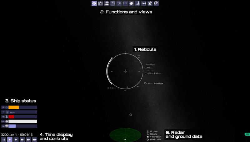
The flight UI or HUD of Pioneer is made of several different parts:
Contents
[hide]Central reticule
Along with the crosshair, the central reticule shows vital flight related information. With the help of them, you can navigate around, perform transits to anywhere without an autopilot.
DeltaV bar
The bars on the left side of the reticule are displaying the deltaV reserves of your ship. They can be thought of as a "fuel" display, since deltaV is the capability of the ship to change speed.
There are two bars there. The left one shows current speed. The right one shows the deltaV capacity of the ship. Beneath it, the fainter bar shows the maximum deltaV capacity.
Under them one finds a numerical display of the deltaV reserves. It shows the % of maximum deltaV (with full fuel tanks), and the remaining deltaV in km/s or Mm/s.
As speed increases, the left bar will start to build up, which shows the speed of the ship proportional to its deltaV reserves. Practically, if the speed bar is bigger than the deltaV bar, you will not be able to slow down and stop, because you do not have enough propellant (fuel). Usually it is wise to keep some in reserve, so there is room for corrections for the unexpected. The autopilot uses about 1/3rd of it for acceleration, another 1/3rd for deceleration, and the remainder is saved.
Orientation displays
There are three orientation displays on the central reticule. There are numerical displays available for each.
- Compass: Shows ship orientation in relation to the cardinal directions of North, East, South, West. Useful if you need to navigate to a downed ship in distress, for example.
- Pitch indicator: Shows pitch relative to the ground. The central tick means you are parallel to the ground, the upper and lower are 90°: looking directly up or down respectively.
- Roll indicator: Shows roll (bank) relative to the ground. The shorter half of the "L"s always point towards the ground. This is also useful in space, where they always point toward the planet or reference frame, so you can easily feel where you need to rotate to find it.
Flight data
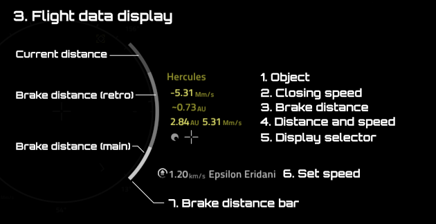
Flight related data are displayed on the sides of the reticule. If the frame of reference data is not shown on the right side, a compact version is shown on the left.
- Name of the object for the displayed data.
- Closing speed. The speed of approach to selected target, which might not be the same as the speed of the ship relative to it. If negative, then you are getting closer to your target, if positive, you are getting further away from it.
- Approximate braking distance, measured in the same unit as the speed. An approximation of the distance needed to slow down to a full stop relative to the target or frame respectively. This is a helpful navigation aid, since it shows how far from your target you need to start decelerating in order to stop close to it target. It is based on the thrust of the main thrusters, so you need to turn your ship around, and decelerate with them. If the distance is smaller than the braking distance, there will not be enough time to stop, causing either an overshoot of target or a crash.
- Distance to the target and relative speed. Measured to its surface.
- Display selector: allows switching the display to show data related to the current frame, navigation target or combat target, respectively. Text color also represents it: Light gray for Frame, Green for Nav target and Red for targeted ships (combat target).
- Set speed display, for the Set Speed flight mode, and the reference object it is measuring the speed relative to.
- Braking distance bar, complementing the braking distance readout. A visual display of your braking distance in relation to the distance to target. There are two bars on top of each other that fill up as you are getting close to your target: a gray one for retro thrusters and a white one for mains. If the white bar is filled up, it's 100%. This is the right time to start decelerating. At 95% it will start to turn green. If it starts to fill up from above with a red bar, then you will overshoot. Only shows if you are getting closer to your target (closing speed is negative). Note that the bar will fill up as you are getting closer to your target, even without any acceleration. Since it represents the proportion of your current distance, it can fill up fast when you are getting close to your target.
You can access the autopilot functions mainly from the reticule. Right mouse on the name of the target, the target itself, or in the system overview panel will bring up the autopilot command. Alt+right mouse on the name on the reticule will bring up the directional holds: Prograde, retrograde, normal, anti-normal, radial in and -out.
Functions and views
There is a row of buttons on the top of the HUD. Several screens and functions can be accessed trough them:
Views and screens
 Internal and external views.
 Info screen: Shows information about ship, pilot, crew, cargo and missions.
 Comms and Autopilot controls. Also used to access starport services.
Maps
 Sector map: for interstellar navigation.
 Orbit map of the current system, or the one selected in the Sector map.
 System overview of the current system, or the one selected in the sector map. Shows general body information, starports, trade and population information.
 Galaxy map: shows the general placement of the current or selected system in the galaxy.
Functions
 Landing gear control and status. Grayed out if it is in movement.
 Engage hyperdrive.
  indicates that jump is illegal in current location (eg. close to starports).
 Rotation damping control and status. If on it will halt ship rotation.
 Switches between equipments and radar at the bottom of the screen. Missiles and ECM are accessible from there.
Flight mode display
 Manual flight.
 Set Speed flight mode. The flight computer tries to maintain the selected speed relative the selected frame of reference.
The autopilot functions bellow are accessible by right clickin on the name of the target either at the reticule, in the system overview list or on the target directly.
 Autopilot: Flying to target.
 Autopilot: Docking with target.
 Autopilot: Entering low, medium or high orbit.
The autpilot functions bellow are accessible by alt+right clicking on the name of the target at the reticule.
 Autopilot: Holding Prograde or Retrograde orientation (with respect to orbit).
 Autopilot: Holding Radial Out or In orientation (with respect to orbit).
 Autopilot: Holding Normal or Antinormal orientation (with respect to orbit).
Ship status
- Weapon temperature. Increases with weapon fire until full, at which point the weapon can not be fired, until it has cooled off. Each fitted weapon (e.g. front and back) has its own gauge.
- Atmospheric pressure. Left number is in % of the hull's pressure tolerance; number on the right is preassure in atm units (Earth sea level pressure)
- Hull temperature, in % of the hull's tolerance. Flying fast in the atmosphere raises it quickly, especially without heat shielding. As with flying with lowered landing gear.
- Hull status in %.
- Shield status in %.
Time controls
Shows the current time and date, and provides time acceleration controls.
Time acceleration levels are:
- || Pause - Pressing it twice will open the Settings window.
- > 1x
- >> 10x
- >>> 100x
- >>>> 1 000x
- >>>>> 10 000x
Depending on the location of the ship, available time acceleration levels can be limited, e.g. near planets. One can still force higher levels pressing the time acceleration button while holding [Ctrl]. However, forcing time acceleration can be dangerous and unpredictable, and it might not switch back to 1x when the autopilot has arrived at its destination.
Radar and ground data
Radar
If the Radar equipment is installed on the ship, a disc shaped planar radar is shown. It shows a representation of the relative position of surrounding ships, stations and objects to the position the pilot's ship.
There are two kinds of radar displays in the game, that can be toggled by pressing [right mouse button] on the radar display.
- 3D Planar: The classical Elite style radar display.
The plane of it shows the plane of the ship, as if it was viewed from up top and behind. The ship is in center, and contacts are shown as small dots. If they are above or bellow the plane of the ship, these dots will have a thin line above or bellow them, indicating their height to the plane.
There are two sizes available, can be switched with the Compact scanner option in the Settings window.
There are some keyboard shortcuts available:
-
- \: Toggle scanner mode. Auto will put the furthermost contact on the edge, and dynamically adjust the range based on that. In manual mode, a specific range can be selected.
- ]: Increase scanner range
- [: Decrease scanner range
- 2D Azimuthal: Projecting the globe onto a 2D plane. It only shows directional data, not distance, but it is omnidirectional.
The range can be adjusted with the [mouse wheel]. The dots fade out as they are getting out of the set range.- The inner circle shows what's in front of the ship.
- The four segmented ring show what is to each side of the ship.
- The outter circle shows what is behind the ship. The circle itself is what is exactly behind.
Ground data
When in the vincinity of a planetary body, the following information is presented:
- Altitude above ground.
- Vetical speed relative to the ground. Positive if gaining altitude, negative if loosing altitude.
- Latitude coordinates.
- Longtitude coordinates.
Indicators
There are several indicators visible on the flight display to aid navigation and orientation: If out of view, the most important ones are also displayed on the inside of the central reticule, to show their direction.
Vector indicators:
 Prograde: The direction of flight. There is a white one for the current frame of reference and also a yellow one for the navigation target if it is moving, when you are not in its frame (like an orbiting space station or planet).
 Retrograde: The opposite of the direction of flight. Likewise, there is a yellow equivalent for this one too.
 Maneuver direction: If there is a maneuver planned in the orbital map, this will show the direction needed to accelerate towards to complete the maneuver. The central reticule will also display the time of burn at the bottom.
 Zenit: The direction away from the center of your reference frame. Useful for blastoff for example.
 Target: Displayed on the center of the selected navigation (yellow) and combat (red) target.
Direction indicators:
These are essentially the crosshairs for each viewing direction (Numpad 8,4,6,2,9,3). They also show up when rotating the view using the middle mouse button.
 Forward crosshair: Points to the front direction.
 Backward crosshair: Points to the rear direction.
 View direction crosshairs: Down, Right, Up, Left. Practically little arrows that are pointing towards forward direction. (e.g.: if the arrow points up, you have to look up for forward view.)
 Direction to front: This is only visible if the view is rotated, and it always points towards the crosshair, so the pilot always knows where forward is.
In-space Indicators
Bodies in space are shown with an icon and a name. If multiple bodies are close together, they are collapsed, and only the most "important" one is shown, with a "+" after its name, to show that it represents multiple bodies.
If you click on a body, you will select it as your nav target (or combat target in case of a ship). You can de-select it by Ctrl-clicking on it. If you click on a body that represents multiple collapsed bodies, you will get a pop-up menu that lets you pick which one you actually want to target.
Icons:


