Difference between revisions of "Making your first ship"
Mikehgentry (talk | contribs) m (→Joining and separating) |
|||
| (29 intermediate revisions by 2 users not shown) | |||
| Line 1: | Line 1: | ||
| + | {{outdated}} | ||
== Overview == | == Overview == | ||
This page describes point by point how to create your first ship, and get it into Pioneer. You should be able to do this from scratch within a few hours, having no experience whatsoever. We aren't intending to cover much detail at all, but will rather give a simplified overview, and point to other pages with fuller explanations for once you're comfortable with the process. | This page describes point by point how to create your first ship, and get it into Pioneer. You should be able to do this from scratch within a few hours, having no experience whatsoever. We aren't intending to cover much detail at all, but will rather give a simplified overview, and point to other pages with fuller explanations for once you're comfortable with the process. | ||
| + | |||
| + | The following article [[Pioneer_Wiki/Making_your_first_ship_scratch]] covers more detailed tips and tricks for ship modelling. | ||
== Prerequisites == | == Prerequisites == | ||
| Line 32: | Line 35: | ||
* Shift-'a', then choose 'Mesh' -> 'Cube' | * Shift-'a', then choose 'Mesh' -> 'Cube' | ||
| − | You've just added a cube to the scene. You won't be able to see it yet, as it's perfectly aligned with the 'default' cube: when you add things they'll appear where the 3D cursor is, and you can move that around with the left mouse button, or snap it back to the grid using the shift-'s' menu. | + | You've just added a cube to the scene. You won't be able to see it yet, as it's perfectly aligned with the 'default' cube: when you add things they'll appear where the 3D cursor is, and you can move that around with the left mouse button, or snap it back to the grid or the centre of the scene using the shift-'s' menu. |
* Move the mouse cursor onto the top down view, then hit 'g' to move the current selection (our new cube). Hold Ctrl to snap it to the grid, and move it a little further in the plus direction along the Y axis (in the direction the green arrow is pointing). Leave it just touching the edge of the default cube | * Move the mouse cursor onto the top down view, then hit 'g' to move the current selection (our new cube). Hold Ctrl to snap it to the grid, and move it a little further in the plus direction along the Y axis (in the direction the green arrow is pointing). Leave it just touching the edge of the default cube | ||
| Line 59: | Line 62: | ||
* Hit 'a' for deselect all. Right click on one of the bottom vertices at the tip of the nose. Hold Shift, then right click on the vertex above it to chain-select it | * Hit 'a' for deselect all. Right click on one of the bottom vertices at the tip of the nose. Hold Shift, then right click on the vertex above it to chain-select it | ||
| + | |||
| + | 'b' for box, 'c' for circle, and Ctrl-left mouse for freehand select are also very useful for selecting multiple things. | ||
| Line 72: | Line 77: | ||
We could equally have used the mouse. 's' for scale and 'r' for rotate work in similar fashion, though note that 'r' toggles between two different rotate modes. | We could equally have used the mouse. 's' for scale and 'r' for rotate work in similar fashion, though note that 'r' toggles between two different rotate modes. | ||
| − | |||
| − | |||
==== Joining and separating ==== | ==== Joining and separating ==== | ||
| − | You'll note that the only vertices you can edit are those belonging to the currently selected mesh - you have to Tab back to 'Object mode' to select another object, then Tab back to | + | You'll note that the only vertices you can edit are those belonging to the currently selected mesh - you have to Tab back to 'Object mode' to select another object, then Tab back to edit mode before its vertices become visible. If we want to 'fill in' the areas between two meshes, we either have to use another completely separate mesh which lines up with the others, copy part of one mesh into the other, or merge them. |
| − | * Tab back to | + | * Tab back to object mode, then hit 'a' key to select all |
* Hit Ctrl-'j' to merge our ship together into a single mesh | * Hit Ctrl-'j' to merge our ship together into a single mesh | ||
| − | If you want to separate off a section, select it in | + | If you want to separate off a section, select it in edit mode, hit 'p' and choose 'Selection' |
==== Creating edges and faces ==== | ==== Creating edges and faces ==== | ||
| Line 92: | Line 95: | ||
Now you can join up the section between the 'wings' and the 'nose'. | Now you can join up the section between the 'wings' and the 'nose'. | ||
| − | * Tab back to edit mode, and chain select two vertices | + | * Tab back to edit mode, and chain select two vertices |
| + | * Hit 'f' to create an edge between them | ||
* Select three edges and hit 'f', and you'll create a face. You can also just select three vertices and hit 'f'; Blender will fill in the edges where needed | * Select three edges and hit 'f', and you'll create a face. You can also just select three vertices and hit 'f'; Blender will fill in the edges where needed | ||
| − | If you want to make things a bit more complicated, try Ctrl-left clicking to create new vertices and edges. You can | + | If you want to make things a bit more complicated, try Ctrl-left clicking to create new vertices and edges. You can 'Subdivide' faces or edges from the panel on the left, or duplicate vertices, edges and faces with Shift-'d'. Extrude (Alt-'e') and Bevel (Ctrl-'b') are also invaluable tools for this kind of modelling. |
| − | If you go wrong, use Ctrl-'z' for undo, or 'Del' key and select 'Only edges & faces'. | + | If you go wrong, use Ctrl-'z' for undo, or select the mistakes, hit 'Del' key and select 'Only edges & faces'. |
=== Cleaning up === | === Cleaning up === | ||
You should now have something resembling a simple space ship. Move things around until you're happy with the basic shape. | You should now have something resembling a simple space ship. Move things around until you're happy with the basic shape. | ||
| + | |||
| + | For a better look, hit 'z' to toggle wireframe view, and numpad '.' to reposition the centre of rotation and zoom around the currently selected object. | ||
| Line 110: | Line 116: | ||
* Switch to vertex edit mode then select all with the 'a' key | * Switch to vertex edit mode then select all with the 'a' key | ||
| − | * Choose 'Remove doubles' on the left-hand | + | * Choose 'Remove doubles' on the left-hand panel. This merges any selected overlapping vertices |
==== Internal faces ==== | ==== Internal faces ==== | ||
| Line 120: | Line 126: | ||
| − | * In this case, it's pretty easy to spot them all with wireframe mode ('z'). | + | * In this case, it's pretty easy to spot them all with wireframe mode ('z'). Select and delete them with 'Del' -> 'Only faces' |
Sometimes the easiest way is just to delete internal vertices and edges - the faces will go with them. | Sometimes the easiest way is just to delete internal vertices and edges - the faces will go with them. | ||
| Line 130: | Line 136: | ||
| − | With more complex models, you'll want to make use of layers to isolate parts of your model. Click or use number keys to activate a layer, Shift-click to activate several | + | With more complex models, you'll want to make use of layers to isolate parts of your model. Click or use number keys to activate a layer, Shift-click or Shift-number key to activate several (Shift-Alt-number key for layers 11 - 20). '`' key (grave aka backtick, probably just left of '1') to show all, and 'm' key to move objects from layer to layer. |
==== Distortion ==== | ==== Distortion ==== | ||
| Line 140: | Line 146: | ||
| − | * Faces with kinks in like the above aren't going to look right | + | * Faces with kinks in like the above aren't going to look right. Delete them |
| + | * Add an extra edge, and recreate them with appropriate triangles | ||
| Line 160: | Line 167: | ||
| − | * In | + | * In edit mode, press 'n' key and switch on 'Normals' for faces in the panel on the right. You might want to make them a bit longer than default |
Normals show you which way your faces have their 'front' sides. Any that look darker than those around them from the outside of the model are suspect, but the acid test is looking for the little blue spikes, which should all point outwards. | Normals show you which way your faces have their 'front' sides. Any that look darker than those around them from the outside of the model are suspect, but the acid test is looking for the little blue spikes, which should all point outwards. | ||
* Chain select any faces pointing the wrong way, then flip them round with the 'Flip Direction' button under 'Normals' on the 'Mesh tools' panel on the left | * Chain select any faces pointing the wrong way, then flip them round with the 'Flip Direction' button under 'Normals' on the 'Mesh tools' panel on the left | ||
| + | |||
| + | You can also use 'Recalculate normals' to try to do this automatically. | ||
=== Thrusters === | === Thrusters === | ||
| + | |||
| + | More here: [[Model system]] | ||
Now is a good time to start thinking about where your thrusters should go. | Now is a good time to start thinking about where your thrusters should go. | ||
| Line 174: | Line 185: | ||
| − | * | + | * In object mode, add an 'Empty' object of type 'Single arrow' |
| + | * Change its name to 'thruster_001' using the 'Outliner' panel on the right | ||
* Duplicate as many as you need, and resize and orient them appropriately | * Duplicate as many as you need, and resize and orient them appropriately | ||
| Line 182: | Line 194: | ||
More here: [[UV coordinates in Blender]] | More here: [[UV coordinates in Blender]] | ||
| + | |||
| + | |||
| + | [[File:First.ship.screen.layout.png]] | ||
| + | |||
* Switch Blender to 'UV Editing mode' using the screen layout widget at the top | * Switch Blender to 'UV Editing mode' using the screen layout widget at the top | ||
| Line 189: | Line 205: | ||
* Chain-select all of the faces on the top of the model, then hit 'u' and choose 'Unwrap' | * Chain-select all of the faces on the top of the model, then hit 'u' and choose 'Unwrap' | ||
| − | A projection of that part of the model will appear in the UV space on the left | + | A projection of that part of the model will appear in the UV space on the left. |
* Do the same for the underside, the sides and the back | * Do the same for the underside, the sides and the back | ||
* Use the 'g', 's' and 'r' keys to squeeze these sections in as tightly as possible to the grid | * Use the 'g', 's' and 'r' keys to squeeze these sections in as tightly as possible to the grid | ||
| + | |||
| + | Use the mousewheel to zoom, and middle mouse button to pan around for a better look. | ||
| Line 198: | Line 216: | ||
| − | Here I've flipped one side of the ship with 's', 'x', '-1', and superimposed both sides. They'll share the same texture. | + | Here I've flipped one side of the ship with 's', 'x', '-1', 'Return', and superimposed both sides. They'll share the same texture. |
* Ensure all faces are selected with 'a', then choose 'UVs' -> 'Export UV Layout' on the menu at the bottom left, and save the file | * Ensure all faces are selected with 'a', then choose 'UVs' -> 'Export UV Layout' on the menu at the bottom left, and save the file | ||
| Line 204: | Line 222: | ||
==== Drawing a texture ==== | ==== Drawing a texture ==== | ||
| − | More here: [[GIMP | + | More here: [[:Category:GIMP|GIMP]], [[Textures]] |
First we find a nice metallic looking 'base' texture with an appropriate license for the background somewhere on the internet. You might not end up with much of it visible in the end, but it's useful to fill in any gaps. I found some on [http://opengameart.org/textures/all opengameart.org]. Grab anything containing a feature you might want as well. | First we find a nice metallic looking 'base' texture with an appropriate license for the background somewhere on the internet. You might not end up with much of it visible in the end, but it's useful to fill in any gaps. I found some on [http://opengameart.org/textures/all opengameart.org]. Grab anything containing a feature you might want as well. | ||
| Line 210: | Line 228: | ||
===== Working with layers ===== | ===== Working with layers ===== | ||
| − | * Open | + | * Open GIMP, and choose 'File' -> 'Open as Layers' |
| − | + | * In the file selector, Ctrl-click on the UV map, the metallic background texture, and any other files you need. Hit 'Open' | |
| − | + | * Use 'Scale tool' to resize the background so it covers the whole image | |
| − | * In the UV map | ||
| − | |||
| − | |||
| Line 229: | Line 244: | ||
* Activate a layer containing some of the details you want to use. Move it higher up in the stack if you want a better view of it | * Activate a layer containing some of the details you want to use. Move it higher up in the stack if you want a better view of it | ||
* Use the select tools to pick out a section you want to turn into a feature | * Use the select tools to pick out a section you want to turn into a feature | ||
| − | * Choose 'Edit' -> 'Copy', 'Edit' - > 'Paste | + | * Choose 'Edit' -> 'Copy', 'Edit' - > 'Paste', then hit the 'New layer' button in the Layers dialogue to create a new working layer for it |
* Use the 'Eraser tool', or use select tools and 'Edit' -> 'Cut' to trim it down precisely | * Use the 'Eraser tool', or use select tools and 'Edit' -> 'Cut' to trim it down precisely | ||
| + | |||
| + | Tab toggles the floating toolboxes. | ||
Note that editing in GIMP is constrained by several things. You can only use tools such as the eraser within the selected area and on the active layer. If you want to draw outside the boundaries of the layer, use 'Layer to image size' in the 'Layer' menu. | Note that editing in GIMP is constrained by several things. You can only use tools such as the eraser within the selected area and on the active layer. If you want to draw outside the boundaries of the layer, use 'Layer to image size' in the 'Layer' menu. | ||
| Line 236: | Line 253: | ||
* Once you've duplicated bits into the shapes you want, use 'Merge down' or 'New from visible' in the 'Layer' menu to merge the parts into a complete layer | * Once you've duplicated bits into the shapes you want, use 'Merge down' or 'New from visible' in the 'Layer' menu to merge the parts into a complete layer | ||
| − | Double click on the | + | Double click on the names of important layers to rename them, to make it easier to keep track of a complex image. |
===== Layer transform tools ===== | ===== Layer transform tools ===== | ||
| Line 244: | Line 261: | ||
| − | * Use Perspective, Sheer, Scale and Flip tools to transform the layer so it matches the shape of the face | + | * Use 'Perspective', 'Sheer', 'Rotate', 'Scale' and 'Flip' tools to transform the layer so it matches the shape of the face |
It's easier if you set the layer you're transforming to invisible. If faces turn out to be distorted or asymmetrical, that isn't a problem. Get the texture to the right shape, and you can adjust the UV map afterwards. | It's easier if you set the layer you're transforming to invisible. If faces turn out to be distorted or asymmetrical, that isn't a problem. Get the texture to the right shape, and you can adjust the UV map afterwards. | ||
| Line 260: | Line 277: | ||
| − | Now we use the 'Heal' and 'Clone' tools to remove anomalies or details we don't want in the image. | + | Now we use the 'Heal' and 'Clone' tools to integrate the separate parts we've pasted in, and to remove anomalies or details we don't want in the image. |
| − | * Hold Ctrl and click on a sample area, that looks how it should. Click and drag over the | + | * Hold Ctrl and click on a sample area, that looks how it should. Click and drag over the target |
Sometimes repeated short clicks seem to work better with heal. With a little practise, you can erase fairly large elements you don't want. It sometimes works better if you turn down the tool's opacity and use multiple strokes. | Sometimes repeated short clicks seem to work better with heal. With a little practise, you can erase fairly large elements you don't want. It sometimes works better if you turn down the tool's opacity and use multiple strokes. | ||
| Line 283: | Line 300: | ||
==== Reimport to Blender (optional) ==== | ==== Reimport to Blender (optional) ==== | ||
| − | You don't need to | + | You don't need to import the texture to Blender to get it into the game, but it can help to get a good look at it first. |
| − | * In Blender's | + | * In Blender's UV editing screen layout, choose 'Image' -> 'Open Image' on the menu on the bottom left |
* Open the finished texture, and make any final adjustments to the UV map | * Open the finished texture, and make any final adjustments to the UV map | ||
| + | |||
| + | Ctrl-tab between editing vertices, edges, faces and islands. | ||
| + | |||
* Switch back to 'Default' screen layout, and switch the right-hand panel to 'Material'. If you included the default cube in your ship, there should already be a material. If there isn't, hit the '+' button to add one | * Switch back to 'Default' screen layout, and switch the right-hand panel to 'Material'. If you included the default cube in your ship, there should already be a material. If there isn't, hit the '+' button to add one | ||
* Switch the panel to 'Texture' mode, click the '+' button to add a texture, then change its type to 'Image or Movie' | * Switch the panel to 'Texture' mode, click the '+' button to add a texture, then change its type to 'Image or Movie' | ||
* Under 'Image' click 'Open', and open the texture | * Under 'Image' click 'Open', and open the texture | ||
* Under 'Mapping' set 'Coordinates' to 'UV' | * Under 'Mapping' set 'Coordinates' to 'UV' | ||
| − | * Set 'Viewport Shading' mode on the menu at the bottom | + | |
| + | |||
| + | [[File:First.ship.viewport.shading.png]] | ||
| + | |||
| + | |||
| + | * Set 'Viewport Shading' mode on the menu at the bottom to 'Texture' | ||
* You might need to make some final adjustments to your thrusters etc. to line them up with the textures. | * You might need to make some final adjustments to your thrusters etc. to line them up with the textures. | ||
| Line 355: | Line 380: | ||
| + | [[Category:Art]] | ||
[[Category:Blender]] | [[Category:Blender]] | ||
| + | [[Category:GIMP]] | ||
Latest revision as of 18:21, 9 December 2020
Contents
Overview
This page describes point by point how to create your first ship, and get it into Pioneer. You should be able to do this from scratch within a few hours, having no experience whatsoever. We aren't intending to cover much detail at all, but will rather give a simplified overview, and point to other pages with fuller explanations for once you're comfortable with the process.
The following article Pioneer_Wiki/Making_your_first_ship_scratch covers more detailed tips and tricks for ship modelling.
Prerequisites
To follow this tutorial you will need:
- A recent copy of Pioneer - using SGModel system. Anything since around Alpha 30 is fine
- A recent copy of Blender - this was written on 2.65
- A recent copy of GIMP - this was written on 2.8
- A three button mouse with a wheel, or equivalent
Other 3D modellers and raster art programs will work fine, as long as you can work with standard formats such as Collada and .png. Other input devices can probably be configured around.
Step by step
Making a ship
More here: Blender
- Open Blender
The default scene should consist of a cube, a camera and a lamp. The camera and lamp are irrelevant and won't be exported, but that cube is going places ;-)
Box modelling
- Make sure the mouse cursor is on the view of the scene, then hit Ctrl-alt-'q' to toggle quad view
This allows us to easily check we have lined things up correctly.
- Shift-'a', then choose 'Mesh' -> 'Cube'
You've just added a cube to the scene. You won't be able to see it yet, as it's perfectly aligned with the 'default' cube: when you add things they'll appear where the 3D cursor is, and you can move that around with the left mouse button, or snap it back to the grid or the centre of the scene using the shift-'s' menu.
- Move the mouse cursor onto the top down view, then hit 'g' to move the current selection (our new cube). Hold Ctrl to snap it to the grid, and move it a little further in the plus direction along the Y axis (in the direction the green arrow is pointing). Leave it just touching the edge of the default cube
The scene's centre, where the default cube currently sits, and where the green and red lines cross, will mark the centre of mass of our ship.
- Make two more cubes, and leave them touching the default cube on either direction on the X axis. You can use Shift-'a' for Add, or Shift-'d' for Duplicate
Editing vertices
- Right-click on the first cube we created to select it
That's the nose of our ship, so it needs to be a bit more pointed.
- Hold the middle mouse button in the 3D viewport, and swing the view round to get a better look at it
Mousewheel zooms, Ctrl or Shift and mousewheel moves a viewport horizontally or vertically, and Shift-middle mouse will pan.
- Hit Tab to switch to 'Edit mode'
You can now Ctrl-tab between vertex, edge and face edit mode. We should be on vertex edit mode already.
- Hit 'a' for deselect all. Right click on one of the bottom vertices at the tip of the nose. Hold Shift, then right click on the vertex above it to chain-select it
'b' for box, 'c' for circle, and Ctrl-left mouse for freehand select are also very useful for selecting multiple things.
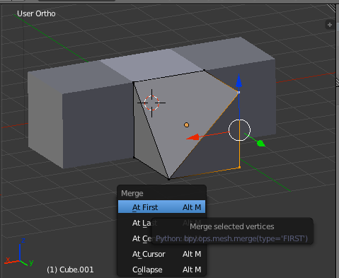
- Hit Alt-'m' for merge, and choose 'At first'
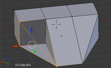
The vertices will merge, and any edges and faces between them are dissolved.
- Do the same for the other two vertices, to create a pointed nose
- We can also make the nose a bit longer, by selecting each of the newly merged vertices then typing 'g', 'y', '2', 'Return', moving them both two Blender units (meters in game) further along the Y axis.
We could equally have used the mouse. 's' for scale and 'r' for rotate work in similar fashion, though note that 'r' toggles between two different rotate modes.
Joining and separating
You'll note that the only vertices you can edit are those belonging to the currently selected mesh - you have to Tab back to 'Object mode' to select another object, then Tab back to edit mode before its vertices become visible. If we want to 'fill in' the areas between two meshes, we either have to use another completely separate mesh which lines up with the others, copy part of one mesh into the other, or merge them.
- Tab back to object mode, then hit 'a' key to select all
- Hit Ctrl-'j' to merge our ship together into a single mesh
If you want to separate off a section, select it in edit mode, hit 'p' and choose 'Selection'
Creating edges and faces
Now you can join up the section between the 'wings' and the 'nose'.
- Tab back to edit mode, and chain select two vertices
- Hit 'f' to create an edge between them
- Select three edges and hit 'f', and you'll create a face. You can also just select three vertices and hit 'f'; Blender will fill in the edges where needed
If you want to make things a bit more complicated, try Ctrl-left clicking to create new vertices and edges. You can 'Subdivide' faces or edges from the panel on the left, or duplicate vertices, edges and faces with Shift-'d'. Extrude (Alt-'e') and Bevel (Ctrl-'b') are also invaluable tools for this kind of modelling.
If you go wrong, use Ctrl-'z' for undo, or select the mistakes, hit 'Del' key and select 'Only edges & faces'.
Cleaning up
You should now have something resembling a simple space ship. Move things around until you're happy with the basic shape.
For a better look, hit 'z' to toggle wireframe view, and numpad '.' to reposition the centre of rotation and zoom around the currently selected object.
While we could move straight onto the textures, we have a little bit of housekeeping due first.
- Switch to vertex edit mode then select all with the 'a' key
- Choose 'Remove doubles' on the left-hand panel. This merges any selected overlapping vertices
Internal faces
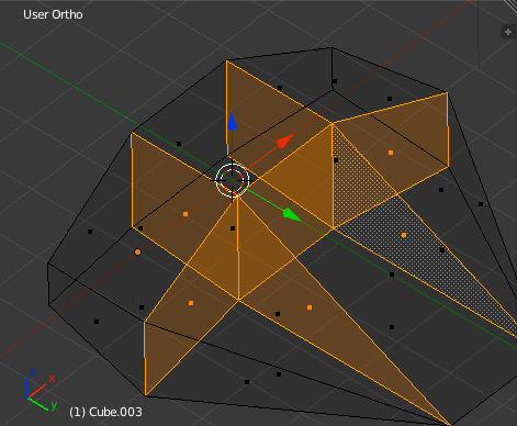
We used the 'short cut' of building our model out of geometric primitives, instead of building it vertex by vertex. This means there are faces inside the model which should never be seen, and to reduce visual glitches, and strain on the renderer, we need to delete them.
- In this case, it's pretty easy to spot them all with wireframe mode ('z'). Select and delete them with 'Del' -> 'Only faces'
Sometimes the easiest way is just to delete internal vertices and edges - the faces will go with them.
You can also hide a face (or vertex, mesh, etc.) with the 'h' key, allowing you to see what's inside your model. Alt-'h' brings everything back. Numpad '/' key toggles 'Local view', hiding all other meshes and objects temporarily.
With more complex models, you'll want to make use of layers to isolate parts of your model. Click or use number keys to activate a layer, Shift-click or Shift-number key to activate several (Shift-Alt-number key for layers 11 - 20). '`' key (grave aka backtick, probably just left of '1') to show all, and 'm' key to move objects from layer to layer.
Distortion
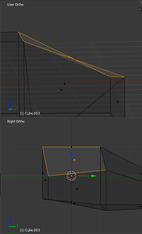
We also need to add in any missing edges to smooth out the geometry. Any polygons whose vertices aren't all on the same plane should be divided into triangles (unless they're going to be curved by setting 'Smooth' shading mode).
- Faces with kinks in like the above aren't going to look right. Delete them
- Add an extra edge, and recreate them with appropriate triangles
Normals
Most faces in Pioneer are only going to have one side. We need to set each mesh to one sided, and check all faces are pointing outwards.
- Switch the mesh to single sided in the right-hand panel's 'Object Data' mode
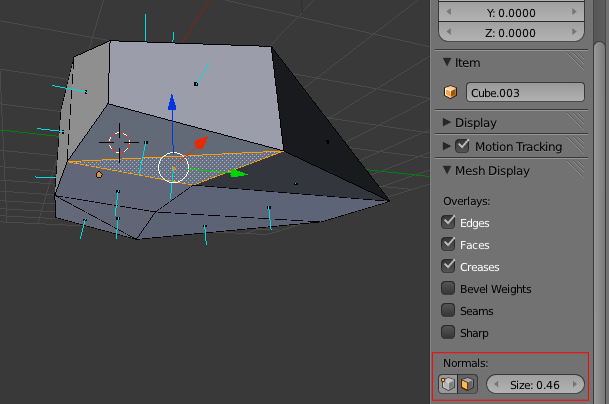
- In edit mode, press 'n' key and switch on 'Normals' for faces in the panel on the right. You might want to make them a bit longer than default
Normals show you which way your faces have their 'front' sides. Any that look darker than those around them from the outside of the model are suspect, but the acid test is looking for the little blue spikes, which should all point outwards.
- Chain select any faces pointing the wrong way, then flip them round with the 'Flip Direction' button under 'Normals' on the 'Mesh tools' panel on the left
You can also use 'Recalculate normals' to try to do this automatically.
Thrusters
More here: Model system
Now is a good time to start thinking about where your thrusters should go.
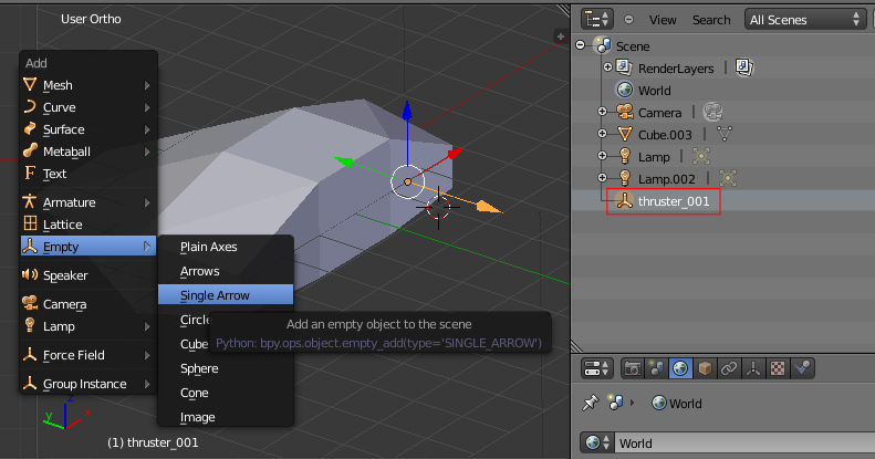
- In object mode, add an 'Empty' object of type 'Single arrow'
- Change its name to 'thruster_001' using the 'Outliner' panel on the right
- Duplicate as many as you need, and resize and orient them appropriately
Textures
UV unwrapping
More here: UV coordinates in Blender
- Switch Blender to 'UV Editing mode' using the screen layout widget at the top
The left half of the screen now represents the way the texture will be mapped onto our model (analogously to the way a shoebox can be flattened out to its 2D plan, or a globe can be projected onto a 2D map).
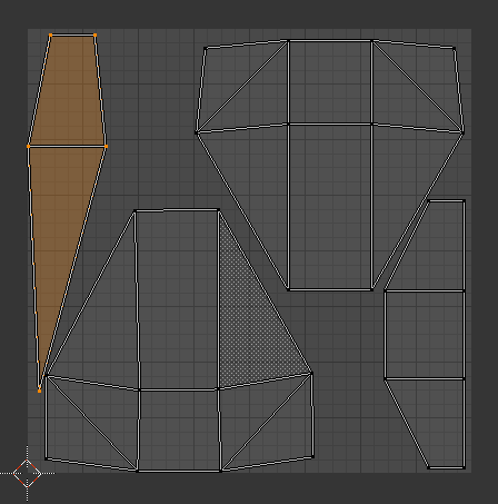
- Chain-select all of the faces on the top of the model, then hit 'u' and choose 'Unwrap'
A projection of that part of the model will appear in the UV space on the left.
- Do the same for the underside, the sides and the back
- Use the 'g', 's' and 'r' keys to squeeze these sections in as tightly as possible to the grid
Use the mousewheel to zoom, and middle mouse button to pan around for a better look.
Here I've flipped one side of the ship with 's', 'x', '-1', 'Return', and superimposed both sides. They'll share the same texture.
- Ensure all faces are selected with 'a', then choose 'UVs' -> 'Export UV Layout' on the menu at the bottom left, and save the file
Drawing a texture
First we find a nice metallic looking 'base' texture with an appropriate license for the background somewhere on the internet. You might not end up with much of it visible in the end, but it's useful to fill in any gaps. I found some on opengameart.org. Grab anything containing a feature you might want as well.
Working with layers
- Open GIMP, and choose 'File' -> 'Open as Layers'
- In the file selector, Ctrl-click on the UV map, the metallic background texture, and any other files you need. Hit 'Open'
- Use 'Scale tool' to resize the background so it covers the whole image
Use the layer controls to keep a handle on what's going on. Each of the resources you've pasted in should normally remain as an unmodified 'master' on a separate layer - we'll create new layers to do the actual editing in. Toggle visibility with the eye icons on the left - here I've set the background metal (known to GIMP as 'Clipboard' layer at the moment) to invisible. Move layers up and down in the stack with the green arrows.
- Move the UV layout to the top of the stack. You'll be using it as a stencil to draw and compose everything else
Copying sections into a working layer
- Activate a layer containing some of the details you want to use. Move it higher up in the stack if you want a better view of it
- Use the select tools to pick out a section you want to turn into a feature
- Choose 'Edit' -> 'Copy', 'Edit' - > 'Paste', then hit the 'New layer' button in the Layers dialogue to create a new working layer for it
- Use the 'Eraser tool', or use select tools and 'Edit' -> 'Cut' to trim it down precisely
Tab toggles the floating toolboxes.
Note that editing in GIMP is constrained by several things. You can only use tools such as the eraser within the selected area and on the active layer. If you want to draw outside the boundaries of the layer, use 'Layer to image size' in the 'Layer' menu.
- Once you've duplicated bits into the shapes you want, use 'Merge down' or 'New from visible' in the 'Layer' menu to merge the parts into a complete layer
Double click on the names of important layers to rename them, to make it easier to keep track of a complex image.
Layer transform tools
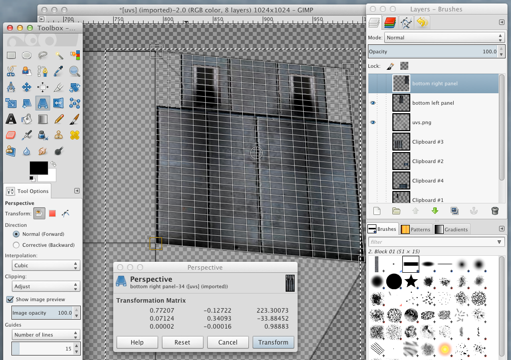
- Use 'Perspective', 'Sheer', 'Rotate', 'Scale' and 'Flip' tools to transform the layer so it matches the shape of the face
It's easier if you set the layer you're transforming to invisible. If faces turn out to be distorted or asymmetrical, that isn't a problem. Get the texture to the right shape, and you can adjust the UV map afterwards.
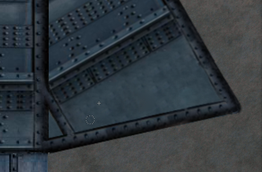
Most of the basic parts are in place.
Healing and cloning
Now we use the 'Heal' and 'Clone' tools to integrate the separate parts we've pasted in, and to remove anomalies or details we don't want in the image.
- Hold Ctrl and click on a sample area, that looks how it should. Click and drag over the target
Sometimes repeated short clicks seem to work better with heal. With a little practise, you can erase fairly large elements you don't want. It sometimes works better if you turn down the tool's opacity and use multiple strokes.
Remember to use the selection tools to limit which part of a layer you are drawing on, so you don't erase or modify parts that are already finished. If you use 'Fuzzy select' to select a region in the UV layer, then switch back to the layer you're working on, you can use the selected area like a mask or a stencil.
Done in a rush, but you get the idea :-)
Hand drawing detail
Use Shift to draw straight lines in GIMP. If you want to draw lots of geometric details, you might want to experiment with a vector drawing program such as Inkscape.
Exporting the texture
- Export the file as a png, remembering to turn off the visibility of the UV layer, and any others you were just using to work with. I've called mine 'firstship.png'
Reimport to Blender (optional)
You don't need to import the texture to Blender to get it into the game, but it can help to get a good look at it first.
- In Blender's UV editing screen layout, choose 'Image' -> 'Open Image' on the menu on the bottom left
- Open the finished texture, and make any final adjustments to the UV map
Ctrl-tab between editing vertices, edges, faces and islands.
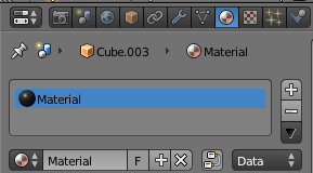
- Switch back to 'Default' screen layout, and switch the right-hand panel to 'Material'. If you included the default cube in your ship, there should already be a material. If there isn't, hit the '+' button to add one
- Switch the panel to 'Texture' mode, click the '+' button to add a texture, then change its type to 'Image or Movie'
- Under 'Image' click 'Open', and open the texture
- Under 'Mapping' set 'Coordinates' to 'UV'
- Set 'Viewport Shading' mode on the menu at the bottom to 'Texture'
- You might need to make some final adjustments to your thrusters etc. to line them up with the textures.
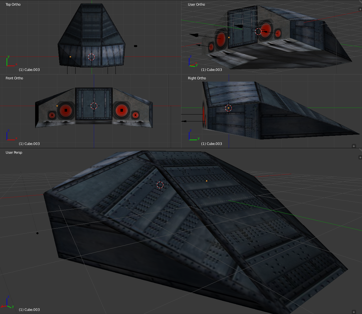
Add some lights to the scene to get a better look.
Not about to win any beauty contests, but hey, she looks like a spaceship!
Using the model
Export from Blender
- Select the mesh, and switch the panel on the right to 'Material'
- Make note of the name of the mesh's material - it will probably simply be 'Material'
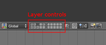
- Select the mesh, and all your thrusters etc. Layer controls might help will this
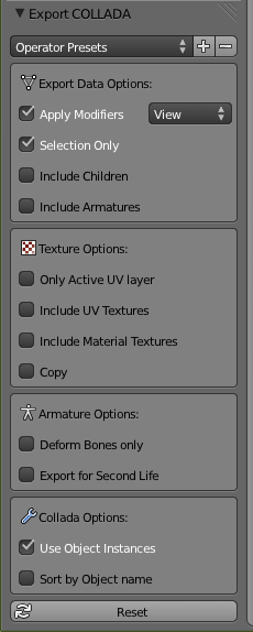
- Choose 'File' -> 'Export' -> 'Collada' in the menu
- Use these export settings. I've saved mine as 'firstship.dae'
Creating a .model file
More here: Model system
- Now create a plain text file (in other words use a text editor rather than a word processor, which would fill it with invisible formatting information etc.) with the extension .model, which describes the ship's appearance
material Material-material
diffuse 1.0 1.0 1.0
specular 0.3 0.3 0.3
tex_diff firstship.png
mesh firstship.dae
- Use the name of the material in Blender, but with "-material" appended to it
- Place the .model, .dae and .png files in a suitable directory such as Pioneer/data/models/ships/firstship/
Load Pioneer's Model viewer, and check everything loads OK.
Getting the model into Pioneer
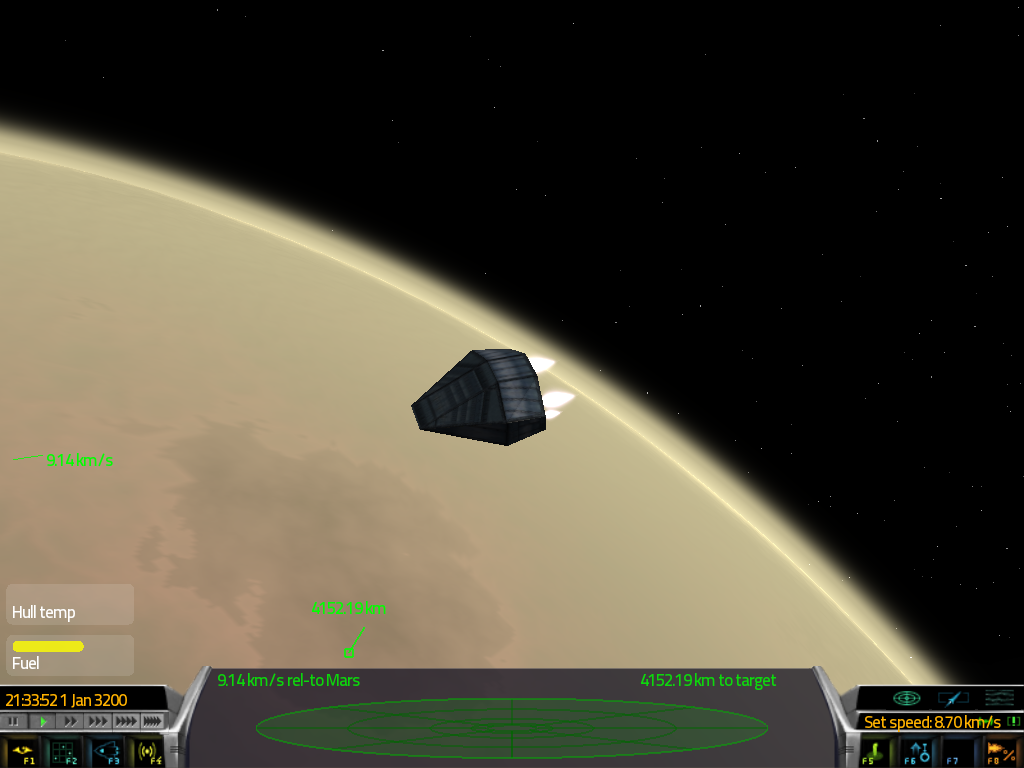
The simplest way to view your model in-game is to replace the model file of the start ship (currently the Wave) with your newly created ship's model file. You'll need to put the .dae and .png in the same directory.
Creating a ship definition
More here: Creating Ships and Stations
...

